S2000 CR Shift Light
For those with 08+ AP2’s, we have the CR lite gauge clusters. It’s something that has bothered me since I’ve owned my S2000, looking at the blank black hole where the power indicator light is on CR’s. I eventually decided it was time to explore the possibilities of enabling this. Upon tear down, I quickly realized that the provision for where the power indicator light is was empty and the black circle on the plastic lens was painted black. Not the main clear lens, but the lenses underneath that form all of the texts and symbols for the cluster. Along with that, I noticed that the solder pads on the PCB where the CR’s light would be was empty. I was at a point where I could decide to try soldering on an SMD and seeing if the PCB is programmed to turn the LED on, or just creating my own shift light system using an Arduino. I chose the latter.
Now this is not exclusive to 08’s, the prismatic lens that runs from the plastic lens to the PCB is identical to the lens for the security light. Most S2000 owners don’t have the factory security system so this light is practically useless. What I did was move this prismatic lens from the security light to where the CR light would be. For 00-07 clusters, you could just keep the location of the security light and add a green LED like I did.
This isn’t really a product I want to package and offer for sale, so I’d like to just share the knowledge that I have. This isn’t so much of a how to guide to follow but just documentation of what I did, however I tried to be as descriptive as possible.
The project code can be found at my GitHub repository: Here
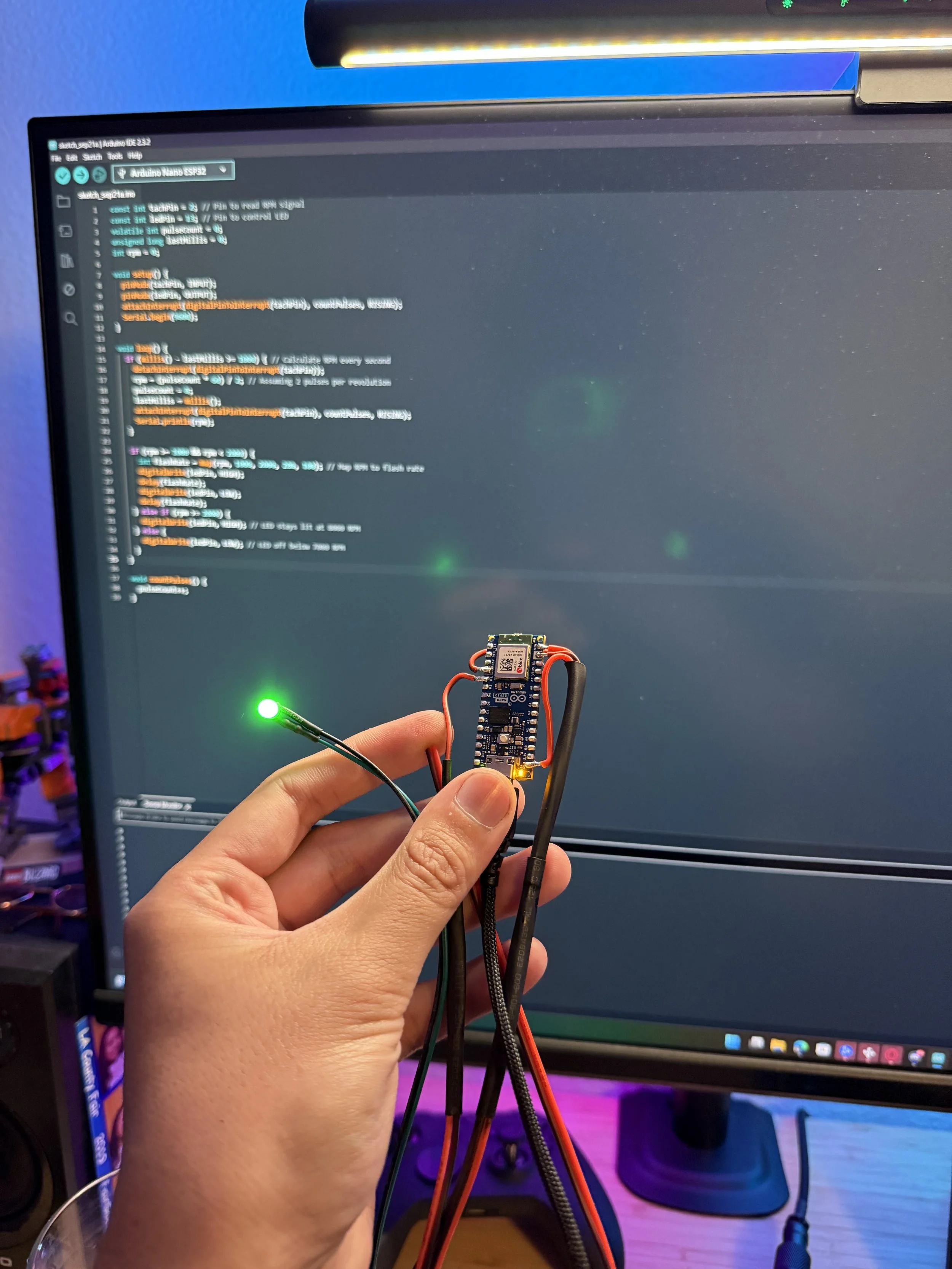
It all started here with a proof of concept, I wanted to make a functioning shift light by telling the Arduino nano to turn on an LED when it receives X input. The Arduino lights up this 5V LED when it detects a certain signal from the tachometer wire of the ECU. In order to safely read the tach signal (which is 12V) I had added a voltage divider in-between the ECU wire and Arduino.
Voltage Divider:
12V Pulsing Signal ---- R1 (4.7kΩ) ---- Arduino Pin (e.g., D2)
|
R2 (2.2kΩ)
|
GND
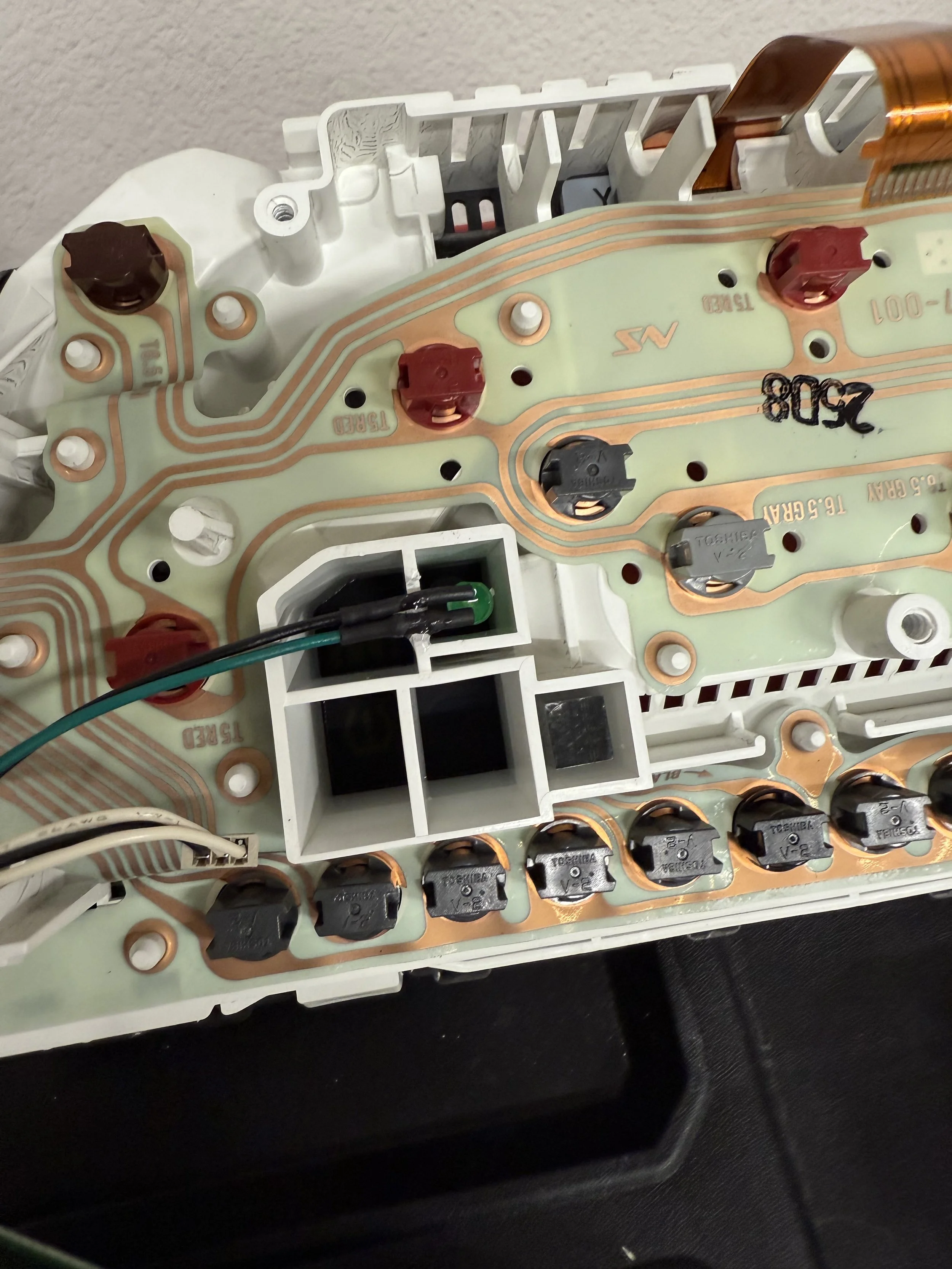
To the right and down of where the green LED is sitting, is the prismatic lens for the security light. While I was mocking everything up I realized the slot for both are the same size and I could just move the lens over to where the CR light should be. I also did further research and found that the CR clusters have this same lens in both slots. Easy done.
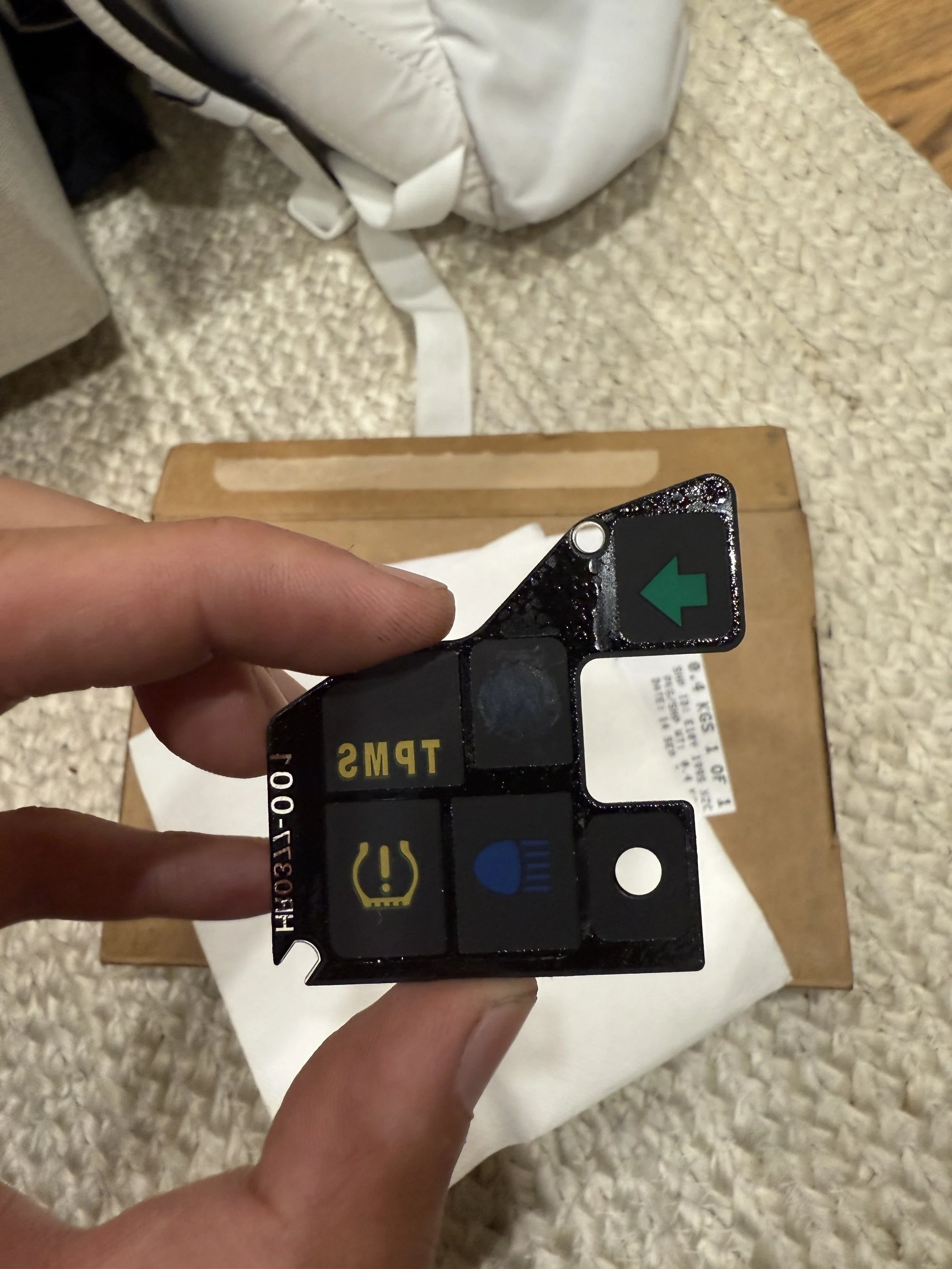
This is the indicator plastic lens that I was mentioning in at the beginning. The circle for the security light is the small one to the right of the high beam. Notice how it is completely clear, this is because the prismatic lens diffracts the light and doesn’t need a colored or opaque layer. The same applies to the CR power indicator light, since it uses the same prismatic lens, I took acetone and slowly wiped away the paint to expose the circle to the right of the TPMS.
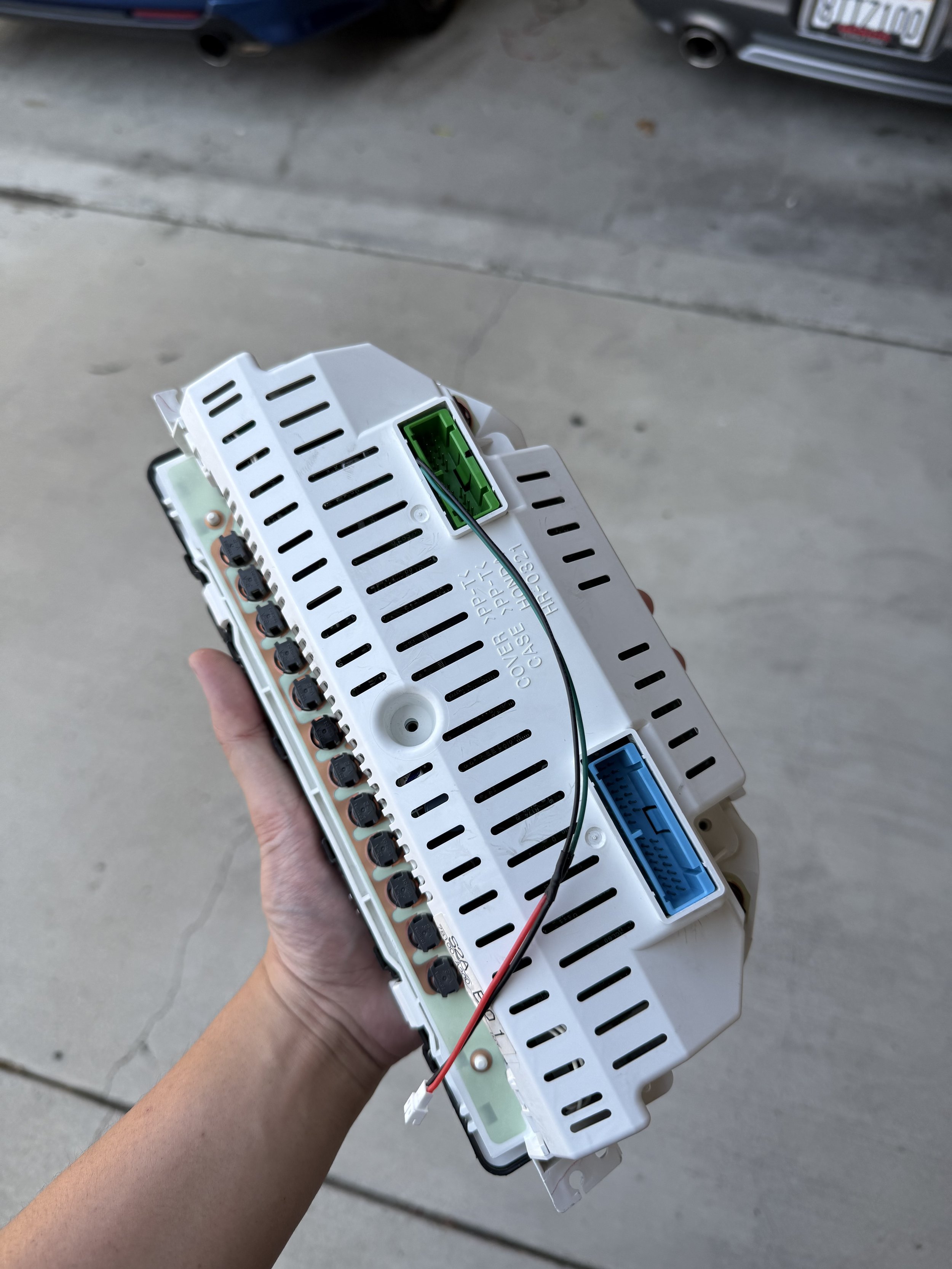
Buttoned everything up, ran a two-wire harness through an opening. These two wires ultimately connect to the Arduino’s LED output and ground pins.
If there’s any questions, you can just PM me in Instagram @APX_Works. Thanks for reading!